Turn any Analog Sensor into an SDI-12 Compliant Sensor Buy Now
SDI-12 Analog Sensor Translator (24 Bit, 4 Channels)
Fully SDI-12 Compliant

Indicator LED for Trouble Shooting

Optimized for Low Power

Rugged, Easy to Mount Case (Optional)
4 Analog Sensor Inputs with 24 Bit Sampling

Voltage or Current Loop Sensor Versions
Features
- Fully SDI-12 Version 1.3 Compliant.
- Simultaneously measures up to 4 sensors with 24-bit resolution using a delta sigma ADC.
- ADC inputs are differential, and can be configured as single sided with a change to the input resistors.
- A wide range of sensor Voltage inputs can be accepted, by modifying the input resistors.
- On board temperature sensor, in addition to the 4 sensor inputs. User must calibrate.
- Low power operation with power consumption at less than 76uA in sleep mode.
- Has the ability to power sensors only when sampling.
- Wide input voltage range.
- Surge protection on sensor inputs.
- Each of the measurements can be adjusted with a scaling factor and offset. (out= scale*V + offset).
- Uses extended SDI-12 commands to set and retrieve all calibration parameters.
- Indicator LED for easy trouble shooting of SDI-12 systems. It can be disabled for low power battery operation.
Applications
- Crop Steering.
- Ultra-fast prototyping of SDI-12 Sensor networks.
- Increasing time to market implementation of sensors.
- Protocol bridging.
SDI-12 Analog Sensor Translator Details
The SDI-12 Protocol Problem
Although SDI-12 is a cryptic hardware and software protocol, it is still a widely used standard interface between environmental sensors and data loggers. Until now, sensor vendors have had the difficult and costly burden of creating their own SDI-12 solutions from scratch. Because of the many eccentricities of the SDI-12 protocol, it is a difficult task to create a truly compliant SDI-12 sensor interface.
The SDI-12 to Sensor Solution
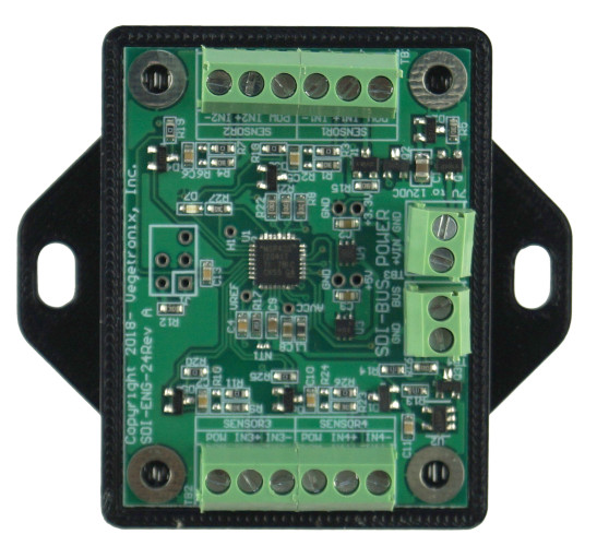
Vegetronix has solved the problem of interfacing sensors to the SDI-12 bus by creating a small SDI12 Sensor Translator board which contains all of the necessary functionality. The SDI-12 Sensor Translator powers the sensor, and samples it with a high resolution ADC when it receives a measurement command from an SDI compliant data logger. The SDI-12 Sensor Translator handles all of the communication, and power down features of the SDI-12 protocol.
Figure 1 shows a connection diagram for utilizing the SDI-12 Sensor Translator. Single sided or differential outputs of up to 4 different sensors are tied to the inputs of SDI-12 Sensor Translator. The Translator contains connection points for power, ground and the SDI-12 data line.
Because of its small size the sensor can often be incorporated into the sensor housing. Alternatively it can be used externally. For sufficiently large quantities, we can provide custom board shapes to fit most any form factor.
Highly Precise 24-Bit Digital Sampling
The translator uses a highly accurate 24 bit analog to digital converter to convert analog data from the 4 channels to digital values.
Customizable for Current Loop Inputs
Many analog sensors have current loop outputs, which have the advantage of being loop powered, and do not suffer signal degradation with long cable runs. The SDI-12 Analog Sensor Translator is normally configured with voltage reading inputs, however, it can be customized to read current output sensors, by changing the input resistor network on the boards. We have instructions below on how to do this, or we can do it for you here at our factory. Just contact us before placing your order to let us know, that you would like this customization option.
Optimized for Low Power Operation
The Translator is extremely low power with only a 76uA current drain when it is sleeping, and it provides sensor power control, so that the sensor only receives power during a measurement cycle. This is useful for creating battery powered sensors.
Diagnostic LED for Fast Troubleshooting
An LED indicator makes initial system configuration and debug easy. The LED will light whenever it receives an SDI-12 command. The LED can be enabled or disabled with an extended SDI-12 X command.
Fully SDI-12 Compliant
All standard SDI-12 commands are supported. In addition, it has extended commands which can be used to calibrate sensor outputs.
Our Translator has been fully tested with the NR Systems SDI-12 Verifier.
Customizable Calibration
Each of the measurements from the 4 input channels can be scaled and offset with user supplied calibration coefficients. This allows you to automatically convert the data, from a voltage into meaningful units.
Internal Temperature Sensor
In addition to all these features the SDI-12 Sensor Translator has an on board temperature sensor, that you can calibrate to your application.
Other SDI-12 Solutions
We carry other useful SDI-12 protocol products that make it easy to get up and running with SDI-12.
We also carry an USB to SDI-12 translator which may be of interest to you. This will turn any computer with a USB port into a SDI-12 compatible data logger.
If you're new to SDI-12, and want a simple, easy to learn, evaluation system to speed up your learning SDI-12, we recommend getting both an SDI-12 Sensor Translator, and an SDI-12 USB translator which can talk to each other.
We also still carry the previous generation legacy 16-bit, 3 channel SDI-12 analog sensor translator. This board costs less, but is larger, only uses 16 bit sampling, has one less channel, higher power, and has a single power output to all of the sensors.
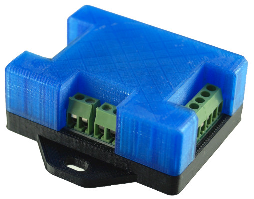
Optional - Easy to Mount Enclosure
To keep the cost low, we sell the board by itself, or you can optionally pair it with an enclosure. The enclosure is made of 3D printed PLA. The top part is of the case is transparent, enabling you to see the internal LED. The bottom part has flanges with mounting holes, making it easy to mount.
You can purchase the case from us for minimal cost, or 3D print your own enclosure, by downloading the SDI-TRANS-SNS24-CASE STL files and printing the case yourself.
Vegetronix Modular Building Blocks
We take a modular approach with our product lines. Each product is simple and low cost, and will easily interface to all of our other products. This approach allows you to build any type of application from our basic set of components.
We Want you to be Happy
Ordering is easy and low risk. Since we build our own products at our factory, all of our products are in stock. When you place your order from our website, it will ship same day from our factory, and you'll have it in your hands in just a couple of days. We ship to nearly EVERY COUNTRY in the world.
If you aren't amazed and delighted by your new SDI-12 Analog Sensor Translator, return it for a refund within 30 days.
SDI-12 to USB Translator with Case. (Case is sold separately)
Figure 1 - SDI-12 Sensor Translator Connection Diagram.
Pricing and Order Information
We ship to nearly EVERY COUNTRY on the planet, directly to you from our factory.
99% of orders ship same day.
| BUY NOW FROM OUR WEBSITE STORE | |||||
| Part Number | Description | Price | Purchase | ||
| SDI-TRANS-SENSOR24 | SDI-12 Volage Sensor Translator (24-bit) | Buy Now | |||
| SDI-TRANS-CURRENT24 | SDI-12 Current Sensor Translator (24-bit). Resistors changed for 4-20mA Current Loops. | Buy Now | |||
| SDI-TRANS-SENS24-CASE | Plastic Case for the SDI-12 Analog Sensor Translator Board (24-Bit). | Buy Now | |||
For volume pricing contact us.
SDI-12 Analog Sensor Translator Specifications
| Sensor Protocol | SDI-12 Version 1.3 |
| Power Supply Voltage | 5.5V to 12V DC |
| Voltage to Sensor | Power supply voltage is switched to the sensor before sampling the sensor. |
| Sensor Input Voltage Range | Nominally 0 to +3.6V (The upper positive voltage is configurable and can be made higher by changing input resistor divider.) The sensor input does not read negative voltages. |
| Internal ADC input range | 600mV |
| Input Resistance | Nominally 200K (Configurable by changing input resistor divider) |
| Sleep Current | 76uA at 9V |
| ADC resolution | 24 bit |
| Number of Sensor Inputs | 4 |
| Sensor Input Types: | Single Sided or Differential |
| Supported SDI-12 commands | aM!, aMC!, aC!, aCC!, aD0!,
aI!, aV!, ?!, a!
See extended SDI commands below. |
| Connections | 3.5mm screwed terminal blocks |
SDI-12 Sensor Translator SDI-12 Command Explanation
For a good background on the SDI-12 protocol see www.sdi-12.org.
The commands assume that the sensor address is 0, but any address could be substituted into the commands below. "\r\n" is carriage return and line feed characters.
Calibration coefficients are modified by extended "X" commands, and are indexed by a 2 dimensional array, where the first zero based index is the measurement index, and the second is the parameter.
| Measurement | Index |
| Sensor 1 | 0 |
| Sensor 2 | 1 |
| Sensor 3 | 2 |
| Sensor 4 | 3 |
| Temperature | 4 |
Each measurement has 3 parameters:
| Parameter | Index | Default Value |
| Offset | 0 | 0.0 |
| scalar | 1 | 1.0 |
| resistor gain | 2 | (Rs+Rp)/Rp (Rp is typically the internal resistance of the ADC, approximately 200 KΩ) |
The internal input resistance of the ADC is approximately 200 KΩ, so the maximum input resistance os 200 kΩ.
Example 1:
If you would like to calibrate the output of the second sensor such that it's voltage is multiplied by 2 and an offset of 3 is added to the result:
out= 2*x+3,
you would use the following two extended commands:
T 0XCOEF[1,0]=3!
T 0XCOEF[1,1]=2!
Each sensor input has a resistor divider circuit which can be used to divide the input voltage from a sensor. The maximum input voltage to the ADC is 600mV, so sensor output voltages must be scaled to this result. See the "Input Configuration" section below.
Example 2:
The Vegetronix THERM200 can be easily converted into a fully compliant SDI-12 sensor, returning temperature in degrees Celsius or Fahrenheit by configuring the translator with the appropriate coefficients.
For Celsius for channel 0 send these commands:
T 0XCOEF[0,0]=-40!
T 0XCOEF[0,1]=41.67!
For Fahrenheit :
T 0XCOEF[0,0]=-40!
T 0XCOEF[0,1]=75.006!
To verify that you've set the coefficents correctly use this sequence of commands:
T 0XCOEF[0,0]!
T 0XCOEF[0,1]!
SDI-12 Command Table
| Command | Description | Typical Response |
| ?! | Returns address of a single sensor on the SDI-12 bus | "0\r\n" |
| 0! | Ping, returns same address | "0\r\n" |
| 0I! | Identification string | "0VEGETRONIXEN24\r\n" |
| 0V! | Verify command. Subsequent 0D0! command will return the version of the Sensor Translator | "00001\r\n" |
| 0M! | Begin a measurement. Subsequent 0D0! command will return the 4 measurements and the temperature. | "00035\r\n" |
| 0MC! | Begin a measurement and respond with CRC on subsequent 0D0! command. | "00025\r\n" |
| 0C! | Begin a concurrent measurement. (Same as 0M! command but no service request is issued.) | "00025\r\n" |
| 0CC! | Begin a concurrent measurement and respond with CRC on subsequent 0D0! command. | "00025\r\n" |
| 0D0! | Get data is called after a 0M!, 0MC!, 0C!, 0CC!, and 0V! commands. If called after the 0V command then the single result is the version number, otherwise it returns 5 results, namely the 4 sensor voltages, and the internal temperature of the sensor translator. | Response to 0V!
"0+2.0\r\n" , Otherwise: "0+1.1+2.2+3.3+25.0\r\n" |
| 0I! | This returns the standard SDI Identification command string response. The first 2 characters after the address are the SDI-12 version, the next 14 are manufacturer and product information, and the last 3 are the software version. | 013VEGETRONIXEN241.0\r\n |
| 0XCOEF[m,n]! | Get the current value of one of the calibration coefficients indexed by m,p, where m is the measurement index[0-3], n is the coefficient[0-2]. The response has the format aX +VAL\r\n where a is the address of the sensor, or an error string if the request is malformed. | "0X +1.0\r\n" |
| 0XCOEF[m,n]=VAL! | Set and store one of the calibration coefficients indexed by m,p, where m is the measurement index[0-3], n is the coefficient[0-2], and VAL is the value of the coefficient. | "0XACK\r\n" |
| 0XLED [ON/OFF]! | This command will turn on or off the LED. If enabled, the LED will blink when ever
it receives an
SDI-12 command from a logger. Normally, the LED is disabled to conserve battery
power, but this features
is useful when trouble shooting systems when they are initially setup. The command
will respond
with the sensor address 'X" and ACK for setting the parameter and "ON" or "OFF" if
you are just
retrieving the current value. Example command: 0XLED ON! will enable the LED. Example Command: 0XLED! will retrieve if the LED is enabled or disabled, (ON/OFF). |
"0XACK\r\n", or "0X ON", or "0X OFF" |
| 0XWARM! | Get the current sensor warm up time. The translator board will apply power to all of the sensors through the lines labeled "POW" on the terminal blocks for this amount of time in milliseconds before taking the reading. | "0X 500\r\n" |
| 0XWARM=VAL! | Set the sensor warm up time. The translator board will apply power to all of the sensors through the lines labeled "POW" on the terminal blocks for this amount of time in milliseconds before taking the reading. For example 0XWARM=500! sets the warm up time to 0.5 seconds. | "0XACK\r\n" |
Sensor Translator Input Configurations and Calibration
Sensors can be connected to the translator through a terminal block. Sensors can be differential, or single ended, depending how the input resistors are configured. The maximum input voltage to the 24-bit delta sigma converter must be below 0.6V, and so a resister divider network must be used to divide down the voltage input, if the sensor voltage is greater than 0.6V.
For single ended and differential mode, we use the internal parallel input resistance of the ADC to form a voltage divider to ensure that the input voltage is below 0.6V. The boards are normally shipped with with the single ended configuration. The 1 MΩ series resistor forms a voltage divider with the inherent 200K input resistance of the ADC, creating approximately a 1/6 voltage divider. For example if you apply 3V to the input terminal of the translator, you will measure approximately 0.5V after the 1 mega ohm series resistor. In this case, the translator should be calibrated with resistor gain of approximately 6.
The 200K input resistance is an approximate value and can vary from device to device, and so to get exact results each channel must be calibrated. If you order standard single input boards with 1 MΩ series input resistors, we factory calibrate each channel for you. If you make changes to the resistor network, then you will need to calibrate the boards yourself.
To compute the exact resistor gain value for each channel, measure the input voltage and the voltage after the series input resistor. Divide the two measurements to get the gain value. Use the extended commands to update the resistor gain value. Test your calibration by sending a measurement command to the translator. The response values should match the measured value on each input channel.
Calibration Example
Suppose you want to recalibrate channel 0 which has a 1 MΩ series input resistor and you have applied exactly 3.00V to the input. The first step is to set the resistor gain coefficent to 1:
T 0XCOEF[0,2]=1!
Then find out the voltage on that channel by taking a measurement command, followed by a data command.
T 0M!
T 0D0!
You can see from the measurement that the value for that channel is 0.512V. The resistor gain calibration coefficient is 3.00V/0.512= 5.859. You would send the following SDI-12 transparent command to update the resistor gain value for channel 0.
T 0XCOEF[0,2]=5.859!
You can verify that you've set the right gain value, by running the measurement and data commands again.
T 0M!
T 0D0!
You should now see a repored value of 3.00V on channel 0.
Custom Board Configurations
Figures 2 and 3, show resistor divider networks for a differential and single ended systems, respectively. Single ended and differential sensors can be mixed on an SDI board. Just let us know which type and the voltage range, before you order.
This online resistor divider calculator is useful for computing resistor values: http://www.daycounter.com/Calculators/Voltage-Divider-Calculator.phtml
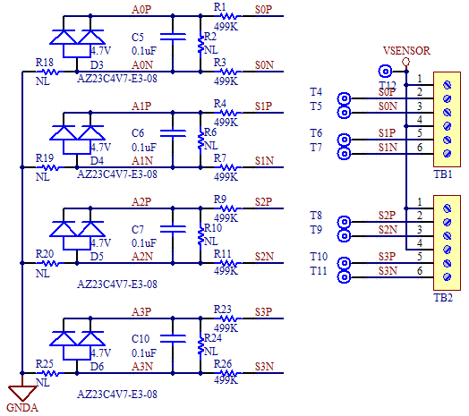
Figure 2: Differential input configuration.
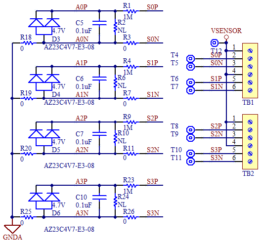
Figure 3: Single ended input configuration.
0 to 20mA Current Sensing
The SDI-12 Translator can also be configured to turn any 0 to 20mA sensor into a fully SDI-12 compliant device. Figure 4 shows how to configure the input resistors. The calibration coefficients should be configured as follows so that the sensor returns it's measurements in milliamps:
out= 50*x+0.
You would send the following transparent commands to the Translator to calibrate it, if the current sensor was on channel 0.
T 0XCOEF[0,0]=0!
T 0XCOEF[0,1]=50!
Retrieve and write down the factory calibrated resistor gain coefficient, in case you want to change change the channel back to a voltage input. Otherwise, you wont be able to go backwards.
T 0XCOEF[0,2]!
Then set the resistor gain coefficient to 1.0
T 0XCOEF[0,2]=1!
The 20 ohm resistors allow currents to be measured from 0 to 30mA. The 20 ohm resistor will generate a voltage output of 0.020V for each 1mA that passes through it. So to convert the output to display in mA we use a multiplier of 50, i.e. (0.001*20*50= 1.0)
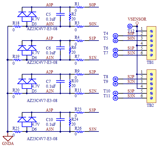
Figure 4: Input Configuration for 0 to 20mA current sensing.
Internal Temperature Sensor
The SDI Sensor Translator has an internal temperature sensor that gives an approximate temperature, however for higher accuracy it must be calibrated by the end user. If you need a better temp sensor use our THERM200 sensor on one of the channels.
The default coefficients can be reset as follows:
T 0XCOEF[4,0]=273!
T 0XCOEF[4,1]=0.483091!
The resistor gain coefficient [4,2] is ignored.
Terminal Block Connections
|
TB1 |
|
| PIN | DESCRIPTION |
| 1 | Sensor 1 Power |
| 2 | Sensor 1 Input(+) |
| 3 | Sensor 1 Input(-) |
| 4 | Sensor 2 Power |
| 5 | Sensor 2 Input(+) |
| 6 | Sensor 2 Input(-) |
|
TB2 |
|
| PIN | DESCRIPTION |
| 1 | Sensor 3 Power |
| 2 | Sensor 3 Input(+) |
| 3 | Sensor 3 Input(-) |
| 4 | Sensor 4 Power |
| 5 | Sensor 4 Input(+) |
| 6 | Sensor 4 Input(-) |
|
TB3 |
|
| PIN | DESCRIPTION |
| 1 | POWER IN (5VDC to 12VDC) |
| 2 | GND |
|
TB4 |
|
| PIN | DESCRIPTION |
| 1 | GND |
| 2 | SDI_BUS |
Board Dimensions
How to Get Started with the SDI-12 Sensor Translator
The best way to try out the SDI-12 Sensor Translator is to order a few samples and connect them to your sensor. The sample board contains terminal blocks for quick connections. Merely connect your sensor inputs to the SDI-12 Translator inputs, connect the Translator to your SDI compliant data logger, and start retrieving data from your sensor.