Convert Any Voltage Sensor Into a Current Loop Sensor Buy Now
Voltage to 4-20mA Current Loop Translator Converter
0-3V Sensor Input

Loop or Externally Powered

4-20mA Current Loop Output

Easy to Calibrate

Easy To Mount

Features
- Low Cost.
- Low Power.
- Factory calibrated limits, which can be re-calibrated in the field with 2 trim pots.
- Interfaces with nearly any voltage output sensor.
- Can power sensors from loop current if the sensor consumes less than 4mA.
- Accepts isolated voltage supply for sensors that consume more than 4mA.
- 4 mounting holes in each corner.
Applications
- Replacement of current sensors with low cost voltage output sensor.
- Interface voltage sensors to PLCs.
- Remote placement of sensors with long cables.
- Interface Vegetronix soil moisture sensors to programmable logic controllers.
- Crop Steering.
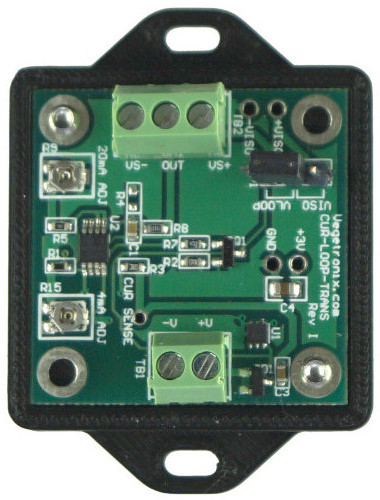
Current Loop Translator Details
Our current loop translator turns any analog voltage output sensor into a 4 to 20mA current loop sensor.
Use Voltage Output Sensors with PLCs
Many types of programmable logic controllers (PLCs) only have current loop inputs, and are incompatible with voltage output sensors.
We developed the current loop translator,because we received many requests to add current loop output capability to our soil sensors so that they could be directly used in PLCs.
Increase Cable Length on Your Sensors
Current loops are useful because extremely long cables can be used with no signal degradation. Cable lengths exceeding 1 kilometer can be run with no degradation or scaling to the signal. Compare this to a voltage output sensor where the resistance of the cable forms a voltage divider and scales down the voltage as the cable length increases.
Output Current is Proportional To Input Current
Current loops provide a sensor output current that is proportional to the sensor's reading. The standard for most current loops is 4mA to 20mA. So the sensor's minimum value corresponds to 4mA and the maximum value corresponds to 20mA. Because the loop never outputs less than 4mA, broken wires or defective sensors can easily be detected. (If the the current is less than 4mA then there is an error.)
Easy Calibration
The current loop translators are factory calibrated with two trim potentiometers, which adjust the 4mA and 20mA limits, respectively. If desired, these can be re-calibrated in the field with a simple calibration procedure which is described below.
The current loop can read voltages up to 3.0V. Higher input voltages can be read, if the sensor voltage is divided by a resistor network.
Loop or External Power of Your Sensors
The translator can directly power sensors that consume under 4mA. For higher power sensors, an isolated external power supply is needed. The translator has 2 solderable holes that can be connected to external isolated power. The translator has a jumper which can switch between loop power, and external isolated power.
The current loop translator can directly loop power the following Vegetronix sensors:
- THERM200
- AquaPlumb
- VG-HUMID
Since the VH400 consumes more than 4mA it must be powered from an external isolated supply.
Optional - Easy to Mount Enclosure
To keep the cost low, we sell the board by itself, or you can optionally pair it with an enclosure. The enclosure is made of 3D printed PLA. The top part is of the case is transparent, enabling you to see the internal LED. The bottom part has flanges with mounting holes, making it easy to mount.
You can purchase the case from us for minimal cost, or 3D print your own enclosure, by downloading the CUR-LOOP-TRANS-CASE STL files and printing the case yourself.
We Want you to be Happy
Ordering is easy and low risk. Since we build our own products at our factory, all of our products are in stock. When you place your order from our website, it will ship same day from our factory, and you'll have it in your hands in just a couple of days. We ship to nearly EVERY COUNTRY in the world.
If you aren't amazed and delighted by your new Current Loop Translator, return it for a refund within 30 days.
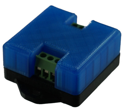
Current Loop Translator with Case. (Case is sold separately)
Current Loop Translator Pricing and Ordering Info
We ship to nearly EVERY COUNTRY on the planet, directly to you from our factory.
99% of orders ship same day.
| BUY NOW FROM OUR WEBSITE STORE | |||
|---|---|---|---|
| Part Number | Description | Price | Purchase |
| CUR-LOOP-TRANS-3 | Voltage to current loop translator with 3V input. | Buy Now | |
| CUR-LOOP-TRANS-CASE | Plastic Enclosure for the Current Loop Translator Board | Buy Now | |
Other Vegetronix Products of Interest
Specifications
| Power consumption | < 100uA |
| Maximum current loop Voltage (Measured across pins of TB1) | 30V |
| Minimum current loop Voltage (Measured across pins of TB1) | 5V |
| Maximum readable sensor input Voltage | 3V (This can be customized) |
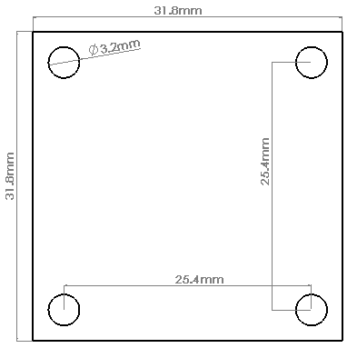
| Dimensions | 2.54cm x 2.54cm (1in x 1in) |
Wiring Table
The boards are marked with the terminal definitions.| Terminal Block TB1 (CURRENT LOOP) | |
|---|---|
| Pin | Description |
| 1 | V-, Current loop negative |
| 2 | V+, Current loop positive |
| Terminal Block TB2 (SENSOR INPUT) | |
|---|---|
| Pin | Description |
| 1 | VS+, Positive sensor Voltage |
| 2 | OUT, Sensor input |
| 3 | Vs-, Negative sensor Voltage |
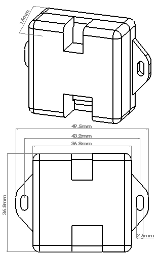
Current Loop Translator Dimensions
Wiring Diagrams
The jumper selects between loop powered sensors, and external isolated power. If the sensor is powered from the loop place the jumper on the VLOOP setting. If the sensor is powered externally, select the VISO setting on the jumper, and solder the power lines to +VISO, and -VISO.
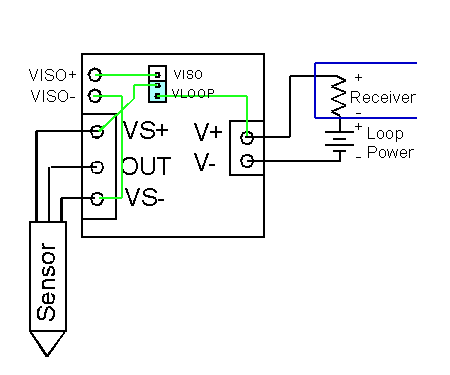
Figure 1. A current loop powered sensor. The green wires show internal PCB connections. With the jumper set to VLOOP the current loop supplies power to the sensor. Note that the current consumed by the sensor must be less than 4mA. The current is measured by measuring the voltage across the external current loop resistor, and dividing by its rated resistance.
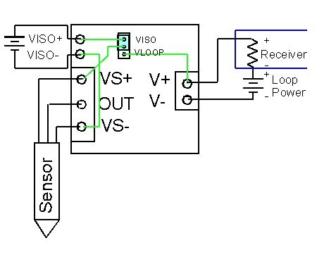
Figure 2. Sensor powered by external isolated voltage supply such as a battery. The green wires show internal PCB connections. With the jumper set to VISO the external battery supplies power to the sensor. Use this configuration if the sensor consumes more than 4mA. Note that VS- and V- must not be shorted directly or indirectly through a ground loop. For this reason the sensor must be powered with an isolated/floating voltage supply such as a battery so that there are no ground loops. The current is measured by measuring the voltage across the external current loop resistor, and dividing by its rated resistance.
Calibration
The current loops are factory calibrated with two trim potentiometers, which independently adjust the 4mA and 20mA limits, respectively.
To perform the calibrations you will need to power the translator with a voltage supply in series with a calibration resistor. A 1% 100 ohm resistor is a good choice. Place the leads of a multimeter across the calibration resistor in parallel, and set the meter to measure voltage. Independently, adjust the 2 trimmer pots with a small screw driver to get the current adjusted correctly for both the 4mA and 20mA limits. For a 100 ohm resistor the multimeter will read 0.4V at 4.0mA and 2.0V at 20mA.
To adjust the 4mA limit, short the sensor input terminals ( OUT, and Vs-) with a wire, and adjust the current across a calibration resistor in the current loop to 4mA.
To adjust the 20mA limit, input 3V into the sensor input terminals (OUT, and Vs-), and adjust the current across a calibration resistor in the current loop to 20mA.
Voltage to Current Equation
Current(mA) = 5.3333*Vin+4Minimum Loop Voltage
The minimum loop voltage can be calculated as follows:
Vloop(min)= Vboard+ Vr+Vw
Vboard is the voltage needed by the current translator board.
Vr is the voltage across the current sensing resistor at 20mA.
Vw is the voltage across the wire at 20mA.
The current loop board requires 5V input voltage from the loop. The voltage across the sensing resistor can be calculated as follows:
Vr= R*0.02A.
Likewise the voltage across the wire or cable can be calculated as:
Vw= (Resistance of wire) * 0.02A
For example, suppose the sensing resistor is 100 ohms, and the cable in the loop is very long and has a resistance of 10 ohms. The minimum loop voltage is calculated as follows:
Vr= 100* 0.02A= 2V
Vw= 10* 0.02A = 0.2V
Vloop(min)= 5V+ 2V + 0.2V= 7.2V
How to Get Started
The best way to get started is to order a few sample current translators and try them out in your application.